
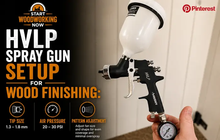
HVLP Spray Gun Setup for Wood Finishing: Tip Size, Air Pressure, and Pattern Adjustment
The single most common HVLP setup mistake is treating it like a pressure problem when it’s actually a volume problem — HVLP guns are limited by CFM (cubic feet per minute of air delivered), not by PSI, and chasing pressure numbers on the gauge while ignoring whether your turbine or compressor can actually supply enough air volume at the gun produces inconsistent atomization no matter how carefully the pressure dial is set. Getting tip size, air volume, and pattern adjustment right before the first stroke on your actual project eliminates the majority of spray finishing defects that get blamed on technique or product quality.
This article is part of the wood finishing guide — covering finish selection, application, troubleshooting, and the equipment that determines application quality.
Navigate to your question
→ What does HVLP actually mean and why does air volume matter more than pressure? → CFM vs PSI — the distinction that explains most setup confusion ↓
→ What fluid tip size should I use for my finish? → Matching tip diameter to measured viscosity, not guesswork ↓
→ How do I set the air pressure correctly? → CFM at the cap, not PSI on the gauge ↓
→ How do I adjust and test the spray pattern before spraying my project? → The cardboard test and what pattern shape tells you ↓
→ What setup mistakes cause orange peel, tip dry, or runs? → Diagnosing setup problems before blaming technique ↓
What HVLP Actually Means — Why CFM Matters More Than PSI
HVLP stands for High Volume, Low Pressure — and the name itself describes the mechanism, though most setup guides skip past it to talk about PSI settings that don’t actually determine atomization quality on their own. HVLP systems atomize finish using a high volume of air at relatively low pressure, compared to conventional spray systems that use lower air volume at much higher pressure to achieve the same atomization.
CFM Is the Real Constraint
The air cap on an HVLP gun needs a specific volume of air flowing through it — measured in CFM — to properly atomize the finish into a fine, even mist. This CFM requirement is fixed by the gun and tip combination, typically in the 8–15 CFM range for fine finishing work on furniture and cabinetry. The air source — whether a dedicated HVLP turbine or a compressor feeding a conversion gun — must be capable of supplying this CFM continuously at the gun, not just momentarily at the tank.
This is where most beginner setups fail before they even start spraying: a small compressor rated for brad nailers and trim guns may show adequate PSI on the gauge but cannot sustain the CFM an HVLP gun needs once the trigger is held down for more than a few seconds. The pressure reading drops as soon as continuous airflow is demanded, atomization quality degrades mid-pass, and the result looks like inconsistent technique when the actual cause is an undersized air supply. Checking your compressor’s CFM rating at the pressure your gun requires — not just its tank PSI rating — is the first setup step, before tip selection or pattern adjustment.
Why Lower Pressure Improves Transfer Efficiency
Transfer efficiency — the percentage of sprayed material that actually lands on the workpiece rather than bouncing off as overspray — is one of HVLP’s genuine advantages over conventional high-pressure spray systems, and the mechanism is straightforward fluid dynamics. At the high air pressures used in conventional spray, atomized finish particles travel at high velocity toward the surface; a meaningful fraction physically bounces off the surface on impact rather than wetting it, becoming airborne overspray. At HVLP’s lower air pressure, particles arrive at lower velocity and wet the surface on contact rather than bouncing, increasing the percentage that actually deposits as finish rather than drifting away as waste.
Typical transfer efficiency figures are around 65–85% for HVLP versus roughly 30–40% for older conventional high-pressure systems. This matters for finishing in two ways beyond material cost: less overspray means less airborne finish particulate to manage from a ventilation and fire-safety standpoint — covered in the dedicated spray finishing ventilation guide covering LEL-based exhaust requirements — and a more even, controllable application with less risk of dry overspray dust settling back onto the wet film.
Choosing the Correct Fluid Tip Size
The fluid tip — the small orifice the finish passes through before atomization at the air cap — determines how much fluid the gun delivers per pass, and getting this wrong is the second most common setup failure after the CFM mismatch above. Tip size needs to match the viscosity of the specific finish being sprayed, not a generic recommendation that ignores how thick or thin that particular product actually is.
Measuring Viscosity Instead of Guessing
A viscosity cup (a small cup with a calibrated hole in the bottom, inexpensive and widely available) measures how many seconds it takes for the cup to empty once filled and lifted — this efflux time in seconds is the practical viscosity measurement that tip size charts are built around. Manufacturers publish efflux time ranges for their products, and many spray finish products list a recommended viscosity range on the label or technical data sheet.
Measuring actual viscosity matters because the same product name can vary meaningfully between batches, after thinning, or at different ambient temperatures — cold finish is measurably more viscous than the same product at typical workshop temperature, which is one of the reasons cold-weather spraying produces inconsistent results even with an otherwise correctly set up gun.
| Finish Type | Typical Viscosity Range | Typical Tip Size |
|---|---|---|
| Shellac, dewaxed sealer | Thin — low efflux time | 1.0–1.2 mm |
| Lacquer, thinned conversion varnish | Thin to medium | 1.2–1.4 mm |
| Water-based polyurethane | Medium | 1.3–1.5 mm |
| Oil-based polyurethane, varnish | Medium to heavy | 1.4–1.8 mm |
| Primer, heavier-bodied products | Heavy | 1.8–2.2 mm |
These ranges are starting points, not fixed rules — the same gun and tip combination behaves differently across manufacturers, and the test spray pattern covered below is what confirms whether the tip size is actually correct for the specific finish in front of you, rather than the chart alone.
Tip Dry — The Symptom of a Tip Too Small or Air Too High
Tip dry — a rough, sandy, or stippled texture in the sprayed film rather than a smooth wet coat — occurs when the ratio of air to fluid at the cap is too high for the fluid being delivered. Atomized particles dry partially in flight before reaching the surface, landing as small dry or semi-dry droplets rather than wetting into a continuous film. This can be caused by a fluid tip too small for the viscosity being sprayed (not enough fluid volume reaching the cap to balance the air volume), air pressure set higher than the tip and viscosity combination calls for, or spraying at too great a distance from the surface, giving atomized particles more flight time to dry before landing.
Setting Air Pressure Correctly — CFM at the Cap, Not PSI on the Gauge
Most HVLP guns specify a recommended air pressure at the air cap (commonly 6–10 PSI for true HVLP, though some gravity-fed conversion guns run somewhat higher), and this is meaningfully different from the pressure reading at the compressor tank or turbine output, because pressure drops along the hose and through the gun’s internal passages before reaching the cap.
Measuring Pressure Where It Actually Matters
An air cap pressure gauge — a small inline gauge that attaches between the hose and the gun, or a dedicated test gauge that fits where the air cap normally sits — measures pressure at the point that actually determines atomization, rather than at the compressor regulator where the reading can be 10–20 PSI higher than what’s actually arriving at the cap, depending on hose length, diameter, and any fittings or filters in the line. Setting the compressor regulator by feel or by a generic “30 PSI” rule of thumb without checking actual cap pressure is a common source of inconsistent results between different shop setups using nominally the same settings.
The Practical Setup Sequence
Set the regulator to roughly the gun manufacturer’s suggested starting point, attach a cap pressure gauge if available, and adjust the regulator until actual cap pressure matches the gun and tip manufacturer’s recommendation for the tip size in use. If a cap gauge isn’t available, the test spray pattern in the next section becomes the primary diagnostic — pattern shape and texture tell you whether the air-to-fluid ratio is correct even without a precise pressure number.
Adjusting and Testing the Spray Pattern
Every HVLP gun has three adjustments that interact: the fan pattern control (round vs wide oval spray shape), the fluid control (how much finish the needle allows through), and the air pressure at the cap covered above. Testing on cardboard or scrap material before touching the actual project is the single most effective habit for catching setup problems before they become defects on the workpiece.
The Test Spray Sequence
Hold the gun roughly 15–20 cm (6–8 inches) from a vertical piece of cardboard or scrap, perpendicular to the surface, and pull the trigger fully for a brief, controlled burst — not a full pass, just enough to deposit a single test pattern. Examine the resulting shape before adjusting anything further.
Test Pattern Diagnostic — What the Shape Tells You
Even, symmetrical oval or fan
Setup is correct for this fluid and air combination — proceed to the workpiece.
Teardrop or banana-shaped pattern
A horn (small air hole) on one side of the air cap is partially blocked, often by dried finish. Clean the cap horns or replace if damaged — this is a hardware issue, not a technique issue.
Heavy centre, thin tapering edges
Fluid output is too high relative to air — reduce fluid control or increase air pressure slightly toward the cap-pressure recommendation.
Speckled, dry, or stippled texture
Tip dry — air-to-fluid ratio too high for this viscosity. Increase fluid output, reduce air pressure, or move to a larger tip size if the finish is heavier than the current tip is rated for.
Re-test after every adjustment rather than changing multiple settings at once — isolating one variable at a time (air pressure, then fluid control, then fan width) makes it possible to identify which adjustment actually fixed the pattern, rather than arriving at a workable setting by trial and error without understanding why it works.
Overlap Pattern on the Actual Workpiece
Once the test pattern is correct, the application pass itself uses a 50% overlap technique — each pass overlapping the previous one by roughly half the pattern width — to maintain even film thickness across the surface. Gaps in overlap produce visible thin stripes once the finish dries; excessive overlap produces runs and sags from doubled film thickness at the overlap zone. This overlap discipline is the spray-application equivalent of maintaining a wet edge in brush application, covered in the polyurethane application guide covering brush technique and lap mark prevention — the underlying goal of even film thickness is identical, even though the technique differs completely between spray and brush methods.
Common Setup Mistakes and How to Diagnose Them
Orange Peel — Usually a Distance or Pressure Problem, Not a Product Problem
Orange peel texture (a bumpy, citrus-peel-like surface rather than a smooth flat film) most commonly results from spraying too close to the surface at too high a fluid delivery rate, depositing finish faster than it can level out before becoming too viscous to flow flat, or from air pressure too low to properly atomize the fluid into fine enough droplets in the first place. Both produce a similar visual result through different mechanisms, which is why diagnosing orange peel requires checking both gun distance and the test pattern from the previous section rather than assuming the product itself is at fault.
Runs and Sags — Excess Fluid, Not Excess Skill Required
Runs and sags occur when too much fluid is deposited in one area relative to how quickly that finish can level and begin to set — commonly from moving the gun too slowly, holding the trigger too long at the start or end of a pass, or fluid output set higher than the surface and finish combination can support without running. Maintaining consistent gun speed and triggering technique (starting the trigger pull before the gun reaches the edge of the workpiece, releasing after it passes the opposite edge) prevents the uneven fluid deposit at pass start and stop points that causes localized runs at the beginning and end of each stroke.
Inconsistent Results Between Sessions — Check the Compressor First
If a previously successful gun setup suddenly produces inconsistent atomization, the most overlooked cause is a compressor that can no longer sustain the required CFM — a contaminated air filter, a developing leak in the line, or moisture accumulation in the tank can all reduce effective air delivery without any change to the gun settings themselves. Before re-adjusting tip size or air pressure on a gun that was previously dialled in correctly, check the air supply side of the system first, since changing gun settings to compensate for a degraded air supply produces a setup that only works until the underlying air supply problem is fixed or worsens further.
For defects that do make it through to a cured finish despite correct setup — orange peel or minor unevenness that wasn’t caught at the test-spray stage — wet-sanding and polishing correct the surface after the fact, covered in the wet sanding polyurethane guide covering the grit progression for levelling spray defects. The same defect appears very differently when caused by brushing rather than spraying — for comparison, see the polyurethane brush marks guide covering brush-specific application defects.
Frequently Asked Questions
Can I use a regular air compressor with an HVLP gun, or do I need a dedicated turbine?
A compressor-fed HVLP conversion gun works fine as long as the compressor can sustain the required CFM continuously at the pressure the gun needs — typically 8-15 CFM for fine finishing work. Many small consumer compressors are rated for intermittent tools like nail guns and cannot sustain this airflow when the trigger is held down continuously. Check your compressor’s continuous CFM rating at the relevant pressure, not just its tank PSI, before assuming a compressor-fed setup will work.
Why does my spray pattern look fine on cardboard but produce orange peel on my actual project?
This is usually a distance or speed inconsistency introduced when working on a larger or more complex surface than the flat cardboard test piece — vertical surfaces, edges, and corners often get sprayed closer or slower than the test pass. It can also indicate the workpiece surface temperature differs from the test surface, since cold surfaces cause finish to begin setting before it levels properly. Re-test on cardboard held at the same temperature as the actual workpiece if temperature is suspected.
Do I need to thin water-based polyurethane for HVLP spraying?
Often, yes, by a small amount (5-10% with water) to bring the viscosity into the range a fine finishing tip (1.3-1.5mm) handles well, though this varies by specific product and your gun’s tip size. Measuring actual viscosity with a viscosity cup rather than guessing a thinning percentage gives more consistent results, since water-based products vary meaningfully between manufacturers and even between batches of the same product.
My gun was working fine yesterday and now the spray pattern is inconsistent — what changed?
Before adjusting gun settings, check the air supply: a partially clogged air filter, a small leak that developed in the hose or fittings, or moisture accumulation in the compressor tank can all reduce effective air delivery without any change to the gun itself. Also check whether finish has dried in the air cap horns since the last cleaning — even a small amount of dried material in one horn produces an asymmetric, banana-shaped pattern identical to a hardware fault.